HDMI Hot Swap Principle and Signal Analysis
Time :2024-04-29 14:58Author :Hangalaxy
With the rapid development of high-definition technology, mainstream computer devices such as audiovisual devices, digital devices, and laptops are equipped with HDMI interfaces. However, there are still many friends who do not understand how to detect hot swapping in HDMI and the use of other HDMI signals. Regarding such issues, Hangalaxy will now explain the signal knowledge of HDMI to you.
Hangalaxy's HDMI series fiber optic cables all have hot swappable functionality. The so-called hot swapping function, in simple terms, can be used without shutting down the system and device power, and can be easily plugged and unplugged without causing damage, greatly enhancing the convenience of use. Hot swapping is a key technology that improves system reliability, fast maintenance, redundancy, and the ability to recover from disasters in a timely manner.
HDMI Hot Plug Detection (HPD)
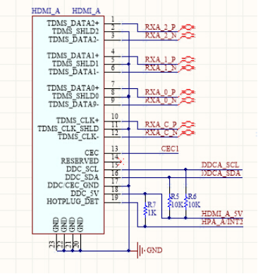
HPD: Hot Plug Detection, abbreviated as Hot Plug Detection. The function of pin 19 of the standard HDMI interface is to detect HPD through hot swapping, which serves as the basis for the HDMI transmitter to determine whether to connect to the HDMI display device for signal transmission.
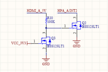
The above diagram shows the interface circuit of an HDMI monitor. When the monitor is connected to the host, the host supplies power to the 18 pin of the monitor - HDMIA_5V, which has a voltage of 5V. HPA_1/INT2 needs to be discussed in two situations:
1. Turn on the monitor; At this point, VCC3V3 has voltage, that is, Q3 conducts and Q2 cuts off. Because HPA_1/INT2 is pulled up to 5V through 1k, this pin is at a high level.
2. The display is turned off; At this time, VCC3V3 has no voltage, that is, Q3 is cut off, Q2 is conductive, and HPAAAA/INT2 is grounded, so HPAAAAA/INT2 is at a low level.
When the host detects that HPA_1/INT2 is at a high level, the host will read the EDID data (extended display recognition data) from the display memory through the data channel DDC (DDC I2C bus). If the operating mode range of the display is detected to be compatible with the graphics card, the host system can activate the TMDS signal transmission circuit (digital video signal transmission circuit) of the graphics card.
HPD voltage requirements:
When the voltage of the HPD pin is greater than 2V, it is judged that the display is connected to the host. When the voltage of the HPD pin is detected to be less than 0.8V, it is judged that the connection between the display and the host has been disconnected.
DDC channel (I2C)
DCC: Display Data Channel. Function: Inform the host of the manufacturer, production date, supported resolution, and other information of the monitor. Purpose: To achieve plug and play.
EDID (Extended Display Identification Data) was originally designed as an optimized display format for PC displays, stored in a dedicated 1Kb EEROM memory (i.e., the EDID data structure is 128bytes).
The biggest difference between HDMI interface and PC display in the EDID data structure of digital TV is that programming data can be multiples of 128Byte. It not only specifies the format of digital TV display, but also specifies digital video signals and digital audio signals. Data outside of the basic 128Byte is additional data, and the 127th byte of the basic data defines the number of additional data blocks for the EDID.